
In-Vessel Irradiation Experiment Facilities at HFIR
The HFIR provides a variety of in-core irradiation facilities, allowing for a wide range of materials experiments and isotope production locations. The facilities below are listed in order from inside the core flux trap to the outside edges of the permanent beryllium reflector. Please refer to the accompanying graph showing the neutron flux values for these regions.
For more information about in-vessel irradiation experiments, contact Chris Bryan.
Experiment Facilities
- Target Regions
- Peripheral Target Positions
- Hydraulic Tube Facility
- Large Removable Beryllium Reflector Facilities
- Small Removable Beryllium Reflector Facilities
- Control-Rod Access Plug Facilities
- Small Vertical Experiment Facilities
- Large Vertical Experiment Facilities
- Slant Engineering Facilities
- Quality Assurance Requirements
Target Regions
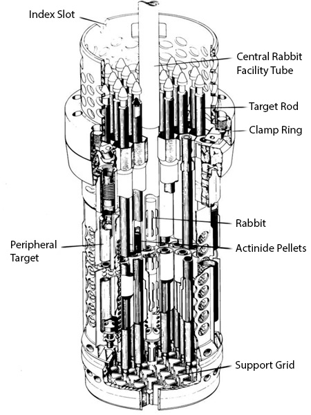
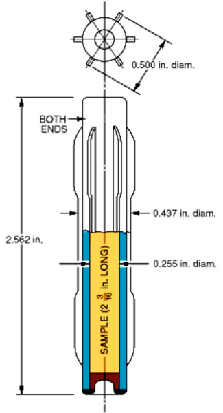
Thirty-one target positions are provided in the flux trap. These positions were originally designed to be occupied by target rods used for the production of transplutonium elements; however, other experiments can be irradiated in any of these positions. A similar target capsule configuration can be used in numerous applications. A third type of target is designed to house isotope or materials irradiation capsules that are similar to the rabbit facility capsules. The use of this type of irradiation capsule simplifies fabrication, shipping, and post-irradiation processing which translates to a cost savings for the experimenter.
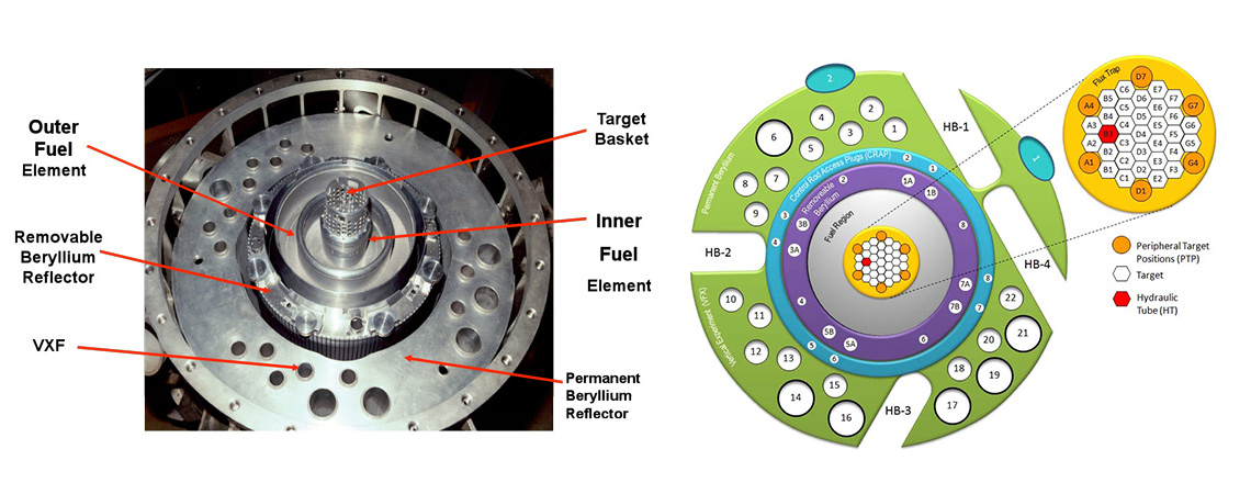
HFIR reactor core assembly and target regions
Target irradiation capsules of each type must be designed such that they can be adequately cooled by the coolant flow available outside the target-rod shrouds. Excessive neutron poison loads in experiments in target positions are discouraged because of their adverse effects on both transplutonium isotope production rates and fuel cycle length. Such experiments require careful coordination to ensure minimal affects on adjacent experiments, fuel cycle length, and neutron scattering beam brightness. Two positions are now available for instrumented target experiments: positions E3 and E6.
Neutron Flux (N/cm2/sec)
| Position | Thermal Flux <0.4 eV | Fast Flux >0.183 MeV |
|---|---|---|
| 1 | 1.7E+15 | 7.9E+14 |
| 2 | 2.1E+15 | 1.0E+15 |
| 3 | 2.4E+15 | 1.2E+15 |
| 4 | 2.5E+15 | 1.2E+15 |
| 5 | 2.4E+15 | 1.2E+15 |
| 6 | 2.1E+15 | 1.0E+15 |
| 7 | 1.7E+15 | 7.9E+14 |
| 8 | 1.1E+15 | 5.1E+14 |
Peripheral Target Positions
Cutaway view of HFIR's fuel element region showing peripheral target positions.
Six peripheral target positions (PTPs) are provided. Fast-neutron fluxes in these positions are the highest available to experiments in the reactor, although a steep radial gradient in the thermal-neutron flux exists at this location.
Like the target positions, a type of PTP capsule is available that houses isotope or materials irradiation capsules that are similar to the rabbit facility capsules. The use of this type of irradiation capsule simplifies fabrication, shipping, and post-irradiation processing which translates to a cost savings for the experimenter.
PTP irradiation capsules of each type must be designed such that they can be adequately cooled by the coolant flow available. Typical experiments contain a neutron poison load equivalent to that associated with 200 g of aluminum and 35 g of stainless steel distributed uniformly over a 20-in. (50.8-cm) length. PTP experiments containing neutron poison loads in excess of that described are discouraged because of their adverse effects on isotope production rates, fuel cycle length, and fuel element power distribution.
Neutron Flux (N/cm2/sec)
| Position | Thermal Flux <0.4 eV | Fast Flux >0.183 MeV |
|---|---|---|
| 1 | 2.5E+15 | 1.2E+15 |
Hydraulic Tube Facility
HFIR hydraulic tube facility
The HFIR hydraulic tube (HT) facility provides the ability to irradiate materials for durations less than the standard ~23 day HFIR fuel cycle, which is ideal for the production of short half-life medical isotopes that require retrieval on demand. The system consists of the necessary piping, valves, and instrumentation to shuttle aluminum capsules (called rabbits) between the capsule loading station and the flux trap in the reactor core.
Heat Considerations
Normally, the heat flux from neutron and gamma heating at the surface of the capsule is limited to 74,000 Btu/h-ft² (2.3 x 10⁵ W/m²). Furthermore, the neutron poison content of the facility load is limited such that the reactor cannot be tripped by a significant reactivity change upon insertion and removal of the samples.
Neutron Flux (N/cm2/sec)
| Position | Thermal Flux <0.4 eV | Fast Flux >0.183 MeV |
|---|---|---|
| 1 | 1.7E+15 | 7.9E+14 |
| 2 | 2.1E+15 | 1.0E+15 |
| 3 | 2.4E+15 | 1.2E+15 |
| 4 | 2.5E+15 | 1.2E+15 |
| 5 | 2.4E+15 | 1.2E+15 |
| 6 | 2.1E+15 | 1.0E+15 |
| 7 | 1.7E+15 | 7.9E+14 |
| 8 | 1.1E+15 | 5.1E+14 |
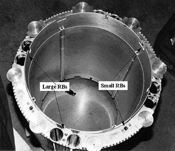
Large Removable Beryllium Reflector Facilities
Large removable beryllium facilities.
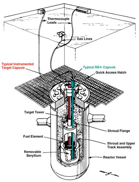
Eight large-diameter irradiation positions are located in the removable beryllium (RB) near the control region and are generally referred to as the RB* positions. These facilities are designed for either instrumented or non-instrumented experiments. The instrumented capsule design can also employ sweep or cooling gases as necessary. Instrument leads and access tubes are accommodated through penetrations in the upper shroud flange and through special penetrations in the pressure vessel hatch.
When not in use, these facilities contain beryllium or aluminum plugs. Because of their close proximity to the fuel, RB* experiments are carefully reviewed with respect to their neutron poison content, which is limited because of its effect on fuel element power distribution and fuel cycle length.
These positions can accommodate (i.e., shielded) experiments, making them well suited for fusion materials irradiation.
Uses for the RB* facilities have included the production of radioisotopes; High Temperature Gas-Cooled Reactor (HTGR) fuel irradiations; and the irradiation of candidate fusion reactor materials. The later type of experiment requires a fast neutron flux. A significant fast flux is present in addition to the thermal flux. For this application the capsules are placed in a liner containing a thermal neutron poison for spectral-tailoring. These experiments are carefully reviewed with respect to their neutron poison content and limited to certain positions to minimize their effect on adjacent neutron scattering beam tubes.
Neutron Flux (N/cm2/sec)
| Position | Thermal Flux <0.4 eV | Fast Flux >0.183 MeV |
|---|---|---|
| 1 | 1.2E+15 | 6.0E+14 |
Small Removable Beryllium Facilities
Small removable beryllium facilities.
Four small-diameter irradiation positions are located in the removable beryllium (RB) near the control region. The small RB positions do not have an aluminum liner like the RB* facilities. When not in use, these positions contain beryllium plugs.
The use of these facilities has been primarily for the production of radioisotopes. The neutron poison content limits and the available pressure drop requirements for experiments in these facilities is the same as in the RB* facilities previously discussed.
Neutron Flux (N/cm2/sec)
| Position | Thermal Flux <0.4 eV | Fast Flux >0.183 MeV |
|---|---|---|
| 1 | 1.2E+15 | 6.0E+14 |
Control-Rod Access Plug Facilities
Eight irradiation positions are located in the semipermanent reflector. The semipermanent reflector is made up of eight separate pieces of beryllium, four of which are referred to as control-rod access plugs. Each control-rod access plug contains two unlined irradiation facilities. Each of these facilities accommodates an experiment capsule similar to those used in the small removable beryllium facilities.
Only non-instrumented experiments can be irradiated in these facilities. When not in use, these facilities contain beryllium plugs. A pressure drop of 10 psi (6.89 x 10⁴ Pa) at full system flow is available to provide primary system coolant flow for cooling experiments.
Neutron Flux (N/cm2/sec)
| Position | Thermal Flux <0.4 eV | Fast Flux >0.183 MeV |
|---|---|---|
| 1 | 1.1E+15 | 1.5E+14 |
Small Vertical Experiment Facilities
Sixteen irradiation positions located in the permanent reflector are referred to as the small vertical experiment facilities (VXF). Each of these facilities has a permanent aluminum liner, located concentric with the core. Normally, non-instrumented experiments are irradiated in these facilities. VXF-7 is dedicated to one of the pneumatic irradiation facilities that supports the Neutron Activation Analysis Laboratory and is unavailable for other use.
A pressure drop of approximately 100 psi (6.89 × 10⁵ Pa) at full system flow is available to provide primary system coolant flow for cooling experiments. When not in use, these facilities may contain a beryllium or aluminum plug or a flow-regulating orifice and no plug.
Large neutron poison loads in these facilities are of no particular concern with respect to fuel element power distribution perturbations or effects on fuel cycle length because of their distance from the core; however, experiments are carefully reviewed with respect to their neutron poison content, which is limited to minimize their effect on adjacent neutron scattering beam tubes.
Neutron Flux (N/cm2/sec)
| Location | Position | Thermal Flux <0.4 eV | Fast Flux >0.183 MeV |
|---|---|---|---|
| Inner | 1 | 7.4E+14 | 5.1E+13 |
| Outer | 1 | 5.1E+14 | 1.8E+13 |
Large Vertical Experiment Facilities
Six irradiation positions located in the permanent reflector are referred to as the large vertical experiment facilities. These facilities are similar in all respects (as to characteristics and capabilities) to the small vertical experiment facilities described in the preceding section except for location and size. When not in use, these facilities contain beryllium or aluminum plugs.
Large neutron poison loads in these facilities are of no particular concern with respect to fuel element power distribution perturbations or effects on fuel cycle length because of their distance from the core; however, experiments are carefully reviewed with respect to their neutron poison content, which is limited to minimize their effect on adjacent neutron scattering beam tubes.
Neutron Flux (N/cm2/sec)
| Position | Thermal Flux <0.4 eV | Fast Flux >0.183 MeV |
|---|---|---|
| 1 | 4.3E+14 | 1.2LE+13 |
Slant Engineering Facilities
Provision has been made for installation of up to two engineering facilities to provide additional positions for experiments. These facilities consist of tubes that are inclined upward 49° from horizontal. The inner ends of the tubes terminate at the outer periphery of the beryllium. The upper ends of the tubes terminate at the outer face of the pool wall in an experiment room one floor above the main beam room.
One of the engineering facilities houses the PT-2 pneumatic tube, which was installed in 1986.
Quality Assurance Requirements
The quality assurance (QA) program for the High Flux Isotope Reactor (HFIR) is based on 10 CFR 830, Subpart A requirements and implementation practices from ASME/NQA-1. All experiments, rabbit capsules, and isotope targets to be irradiated in HFIR must be designed and fabricated under an equivalent set of controls. The experiment’s quality program will be reviewed for approval by the Research Reactors Division (RRD) QA personnel prior to acceptance of an experiment into the irradiation program. Experimenters are expected to exercise strict controls over material certification, traceability, and handling, fabrication dimensional tolerances and inspection, containment integrity testing, and cleaning.
The specific design of the experiment will be reviewed and approved by RRD technical personnel following an established process. Deviations and nonconformances to approved designs are required to be reviewed and approved by RRD. Experiment fabrication facilities may be audited by RRD QA personnel for program implementation compliance. The experiment’s fabrication records will be reviewed and approved prior to acceptance of the hardware for irradiation in HFIR.