The Science of the Neutron Spin Echo Spectrometer

Main Features

NSE is of the original generic IN11 kind, which is the technique with the largest potential to extend the resolution beyond current limits. The instrument possesses a number of unique features:
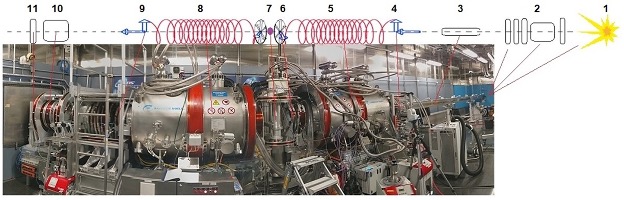
  • Ultrahigh resolution: τ_max ≤ 350 ns (Δħω = 2neV)
  • Huge dynamical range extending up to 1:10^6
  • Field compensation and magnetic shielding for high magnetic stability
  • Highest Q resolution ΔQ/Q = 1%

A moderator detector distance of 18 m yields a frame width of Δλ = 0.366 nm. The resolution of τ_max= 350 ns shall be obtained for λ > 1.8 nm (g = 1.8). In addition, due to the TOF λ separation the wavelength dependent part of the Q-resolution is an order of magnitude better than at reactor instruments [3]. Exploiting that the Fourier time τ∼λ^3 a subsequent use of various frames covering 0.25 < λ/nm < 2.0 and a variation of the magnetic field (integral) by a factor >1000 a huge dynamical range is achieved. By automatic setup procedures, the change of wavelength frames will be a routine operation with negligible time delay. The inherent change of Q(λ)∼1/λ fortunately complies with the usual dispersion of relaxation rates Γ∼Q2.Q4. An area-sensitive fast detector of 30 cm in diameter covers a solid angle of ΔΩ > 4° × 4° and ensures an efficient data collection rate. The magnetic stray field of the main coils is compensated down to 1 to 1.5 × 10⁻⁴T in a 1.5m distance. Thereby, it becomes possible to enclose the instrument area by a magnetic shielding, which ensures a stable and reliable operation. The latter also depends on a rigid mechanical design. The thus achieved signal stability is an utterly important but often overlooked quality.

The placement of components along the beam line is shown in one of the publications. The neutron guide section starts with the shutter insert at about 2.5 m distance from the cold coupled moderator. Guides are Ni-coated and have a cross section of 4 cm (width) × 8 cm (height). A chopper system consisting of four choppers selects the required wavelength frame. Between the first and second chopper a short polarizing bender is located that introduces a bend of the beam line of 3.5° out of the direct line of sight. For different wavelength ranges —each covering several frames—different solid state microbenders are required. For that purpose, 3 benders are situated in a revolver. A fourth position of the revolver (length ∼0.5 m) serves as auxiliary shutter. After the benders a guide field in the neutron guide field preserves the polarization. Between the last (4rd) chopper the guide field is rotated from vertical to longitudinal direction. The expected flux on the sample has been determined using the VITESS Monte-Carlo code, the result is shown at left. The time-averaged intensity on the sample will be respectively higher than the flux at the high flux ILL instrument IN11. The maximum Fourier time of 350 ns requires the use of long wavelengths up to 1.8 nm in combination with a large magnetic precession field (1 Tm).

The "primary" shielding sector around the neutron guide ends at about 10 to 11 m. The following NSE area is enclosed by a combined magnetic and radiation shielding. The functional components are located on three separate mechanical carriers: first arm, sample stage, and second arm. The carriers move on air pads on a special granite floor (tanzboden). The main solenoids, one on each arm, each consist of two concentric cylindrical superconducting coils that provide high field integrals in combination with compensation for lowest stray field. Flippers limit the precession paths. They are operated with current ramps that are adapted to the time varying wavelength within the selected frame. For low Q-SANS, an optional converging collimator in front of the sample is installed.

After traversing the last π/2-flipper, the neutrons enter a combination of background suppression collimator and the analyser, before those with the right final spin polarization hit the detector. The scattering arm has to be rotated around the sample position in order to realize a reasonable momentum transfer (Q) range. This determines the lateral space requirements. The instrument use has to be restricted to a maximum scattering angle of about 83° in order not to violate its sector boundaries.